RGB Light Control for Mobile: Widget Functionality and Code Examples
Try out the RGB Control Widget with this demo project. With this widget you can dynamically set the color, turn the RGB on/off, set the brightness, and choose custom animation effects.
Published
February 15, 2024
Author
Mark Kiehl
Are you into blinking? Then you'll love the RGB Control widget! We teamed up with our experienced community member to create code examples, so you could try the functionality of this widget for yourself. Enjoy!
This mobile widget allows you to control an RGB connected to your hardware. You can dynamically set the color, turn the RGB on/off, set the brightness, and choose custom animation effects. You can find a basic description of the widget in our documentation.
Here's what you'll find in the code example:
RGB light control
Gamma correction of the RGB color
Functions for conversion between the RGB and HSL (hue, saturation, luminance) color models
Full range of animation mode options
What you need
Adafruit Feather HUZZAH ESP8266 board
Common anode RGB LED
Resistors for each LED pin (usually around 220-330 Ω)
Breadboard and jumper wires
Arduino IDE with ESP8266 support installed
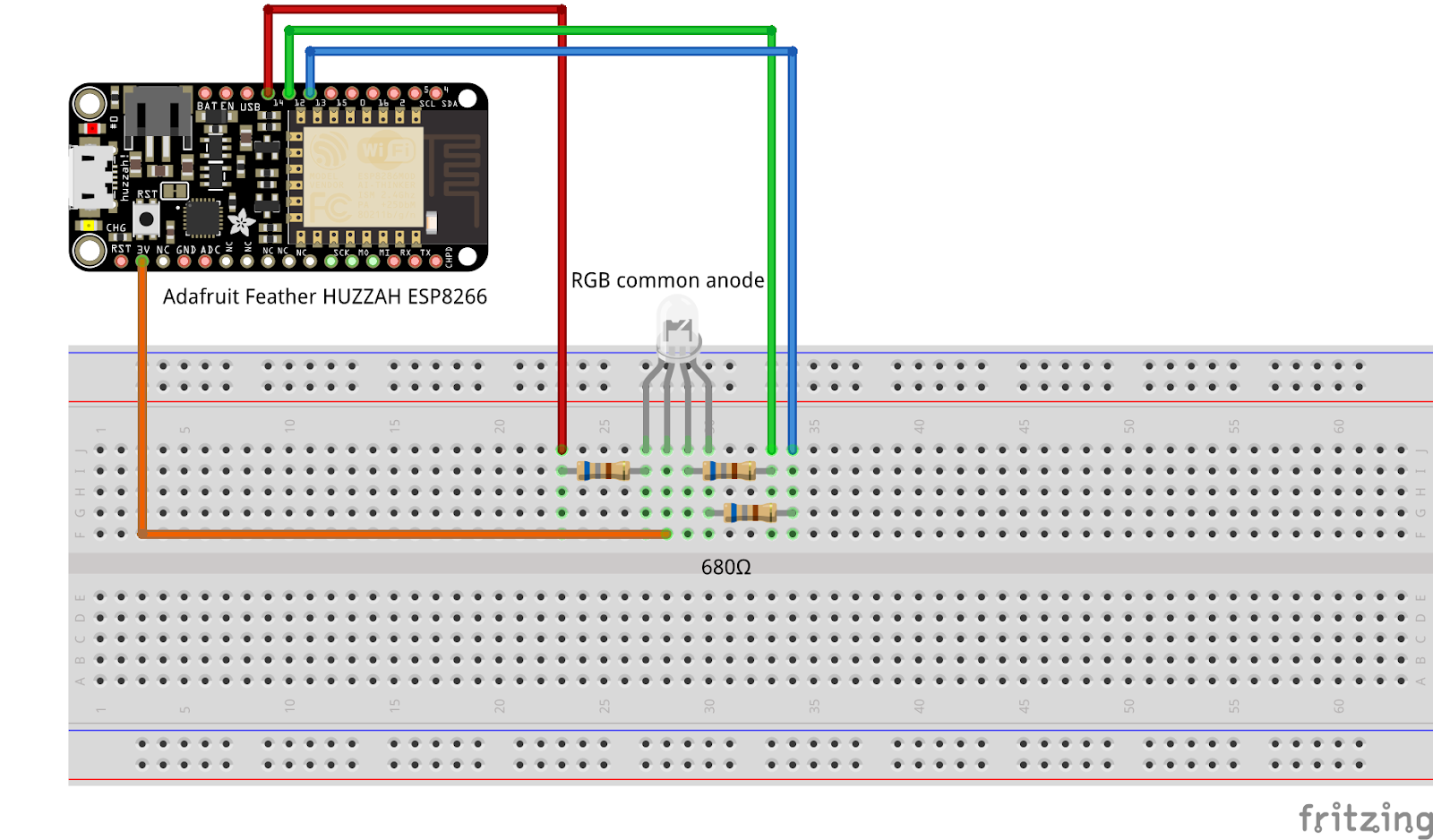
Wiring up the RGB LED with ESP8266
Connect the common anode of the RGB LED to the 3.3V pin on the ESP8266.
Connect the red, green, and blue pins of the LED to the PWM pins on the ESP8266 (in this example, GPIO14, GPIO12, and GPIO13) through resistors.
Firmware and template configuration
Template and Datastreams Setup
Create a new Template and get the basic firmware that enables communication between the ESP8266 board and Blynk. We recommend using Blynk.Edgent firmware examples to access WiFi provisioning via app and FOTA updates.
Add the following Datastreams in your Template:
V10 for Button (On/Off control)
V2 for Color selection
V6 for Brightness control
V5 for Animation speed
Enable "Sync with latest server value" and "Save raw data" for V10, V6, and V5.
Now you are all set to experiment with the functionality of the RGB Control Widget!
RGB LED Configuration and Gamma Correction
This section of code is responsible for managing the color and brightness of an RGB LED connected to an ESP8266 board and a gamma correction.
Gamma Correction Setup: const bool GAMMA_CORRECT = true; enables gamma correction. The gamma correction table (gamma8) is used to adjust the perceived brightness of the RGB LED to match how human eyes perceive light.
Gamma Correction Table: const uint8_t PROGMEM gamma8[] = {...}; is a lookup table containing 256 gamma-corrected values. This table is used to translate linear brightness values into nonlinear values that more closely align with human vision.
Pin Assignments: The PIN_RED, PIN_GREEN, and PIN_BLUE constants define which GPIO pins of the ESP8266 are connected to the red, green, and blue leads of the RGB LED, respectively.
RGB and Brightness Variables: Variables rgb_red, rgb_green, rgb_blue, and rgb_brightness store the current color and brightness levels of the RGB LED.
LED Type Configuration: #define COMMON_ANODE indicates that the connected RGB LED is of the common anode type. The MAX_COLOR_VALUE constant is set to 255, representing the maximum value for each color channel.
Color Conversion Structures and Functions: The HSL_t and RGB_t structures represent color in HSL (Hue, Saturation, Luminance) and RGB formats, respectively.rgb2hsl and hsl2rgb functions are used for converting between RGB and HSL color formats.
setRGB Function: The setRGB function applies the desired RGB color and brightness to the LED. It uses the gamma correction table if enabled, adjusts the RGB values based on the luminance setting, and accounts for whether the LED is common anode or common cathode. The function ultimately writes the adjusted color values to the appropriate pins using analogWrite.
RGB Control Widget
Integrating the hardware setup with the Blynk app, allowing you to control the LED remotely. The code manages different control modes, interprets user inputs from the Blynk app, and adjusts the LED's behavior accordingly.
Variable Definitions: Variables like rgb_light_control_mode, animation_fade_strobe, rgb_color_white_mode, and others are defined to keep track of the current state of the RGB LED, such as its color, brightness, and animation settings. These variables are updated based on user interactions with the Blynk app.
Virtual Pins:
BLYNK_WRITE(V10): Responds to changes on virtual pin V10. It controls the on/off state of the RGB LED.
BLYNK_WRITE(V2): Handles updates to virtual pin V2, linked to a color picker widget in the app. It allows users to change the LED's color and supports different modes (color, white, animation).
BLYNK_WRITE(V6): Linked to a slider widget for adjusting brightness, this function updates the LED's brightness based on changes to virtual pin V6.
BLYNK_WRITE(V5): Controls the animation speed of the LED, responding to adjustments on virtual pin V5, often linked to a slider for setting animation speed.
Serial Communication: Throughout these handlers, the code uses Serial.print statements to output the current state and changes, aiding in debugging and providing feedback on the device's status.
LED Control Logic: The setRGB function is called with appropriate parameters to update the LED's color and brightness. This function applies the settings based on the current mode (color, white, or animation) and user inputs.
Configuration of RGB LED and Blynk Cloud Sync
BLYNK_CONNECTED(): This function is called every time the device successfully connects to the Blynk cloud service. You can update your hardware to the latest datastream value from Blynk.Cloud after your hardware went offline, and then came online again. Use Blynk.syncVirtual() to update a single virtual pin, or Blynk.syncAll() to update all virtual pins. See State Syncing for more details.
Initializing RGB LED Pins: pinMode(PIN_COLOR, OUTPUT); set the digital pins connected to the red, green, and blue components of the RGB LED as outputs. This allows the microcontroller to control the brightness of each color in the RGB LED.
Setting Initial RGB Values: setRGB(0, 0, 0, 0, GAMMA_CORRECT); calls a function that initializes the RGB LED with all color components (red, green, blue) set to 0 (meaning the LED is off). It also passes the current brightness value (also 0) and the status of gamma correction (enabled or disabled).
Initializing Color and Animation Modes: The variables rgb_color_white_mode, rgb_animation_left, rgb_animation_right, and rgb_animation_top are structures that store RGB values. Here, they are all initialized with red, green, and blue values set to 0. These structures are used to store and handle different color and animation modes as controlled through the Blynk app.
Hope you enjoyed blinking with RGB control and the code examples were helpful - we will be happy to hear your feedback on the community forum.
Sign up for a newsletter
Get latest news from Blynk
Over 500,000 people already signed up our newsletter. We never spam.
Thank you! Your submission has been received.
Oops! Something went wrong while submitting the form.


.png)


