Blueprint is a pre-configured template on the Blynk IoT platform, that will help you create a fully functional project in a few minutes. It already includes mobile and web dashboard UI, working firmware, and a tutorial to help you connect your device to the Blynk IoT platform and control it from the app!
On this page you can review the blueprint to have an idea of the ready project you are going to get. Sign up for a free account on the Blynk IoT platform to try it out.
Introduction
This blueprint will guide you through launching your project with the XIDE IoT Framework.
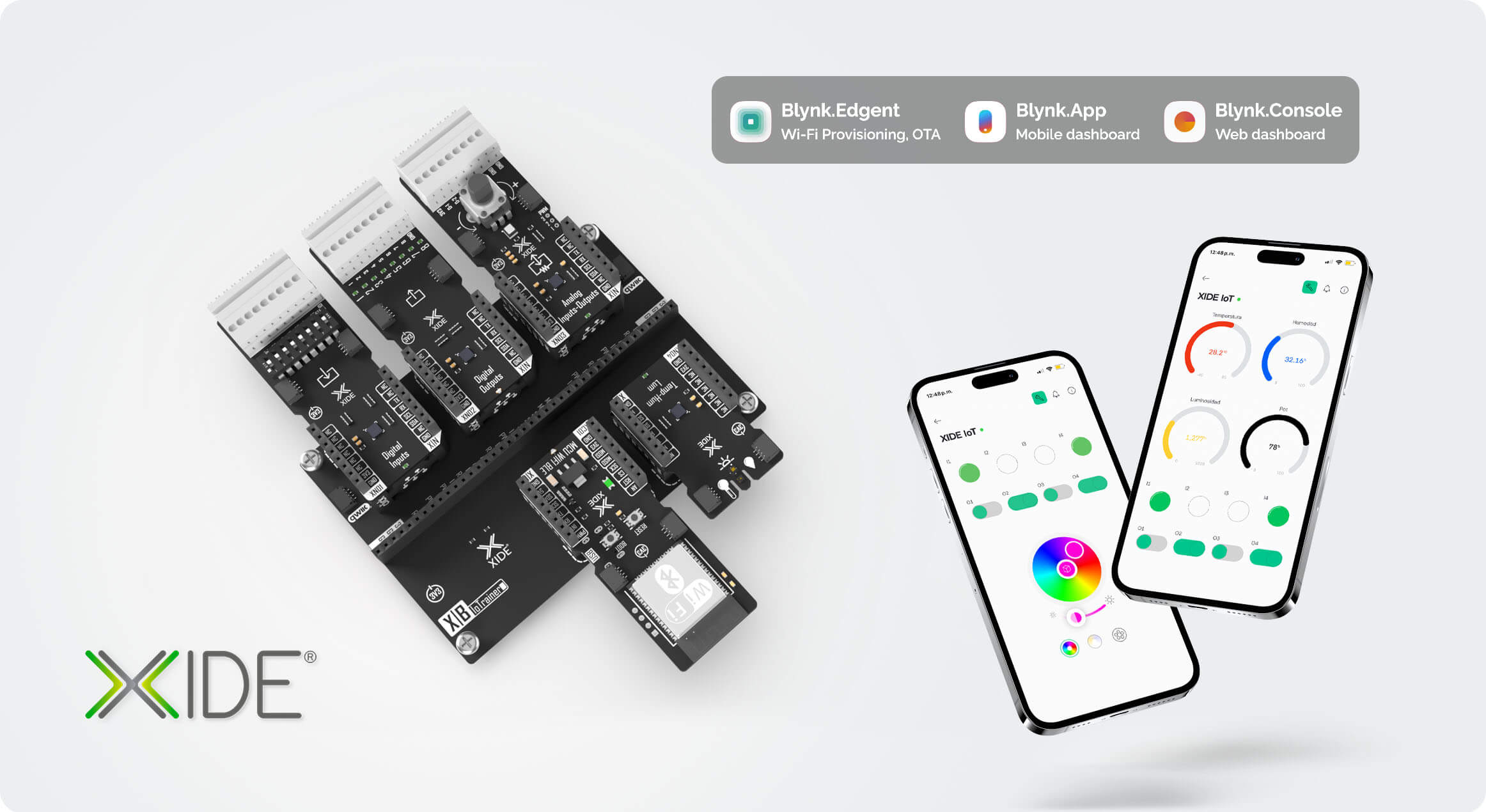
The sample project uses the following devices from the Kit XIDE IoT, which allows to measure temperature, humidity and ambient ligth, read four switchs, one potentiometer position, 3 analog signals, control four digital outputs and one RGB led.
Blynk Console and Blynk App for web and mobile dashboards
How To Use This Blueprint
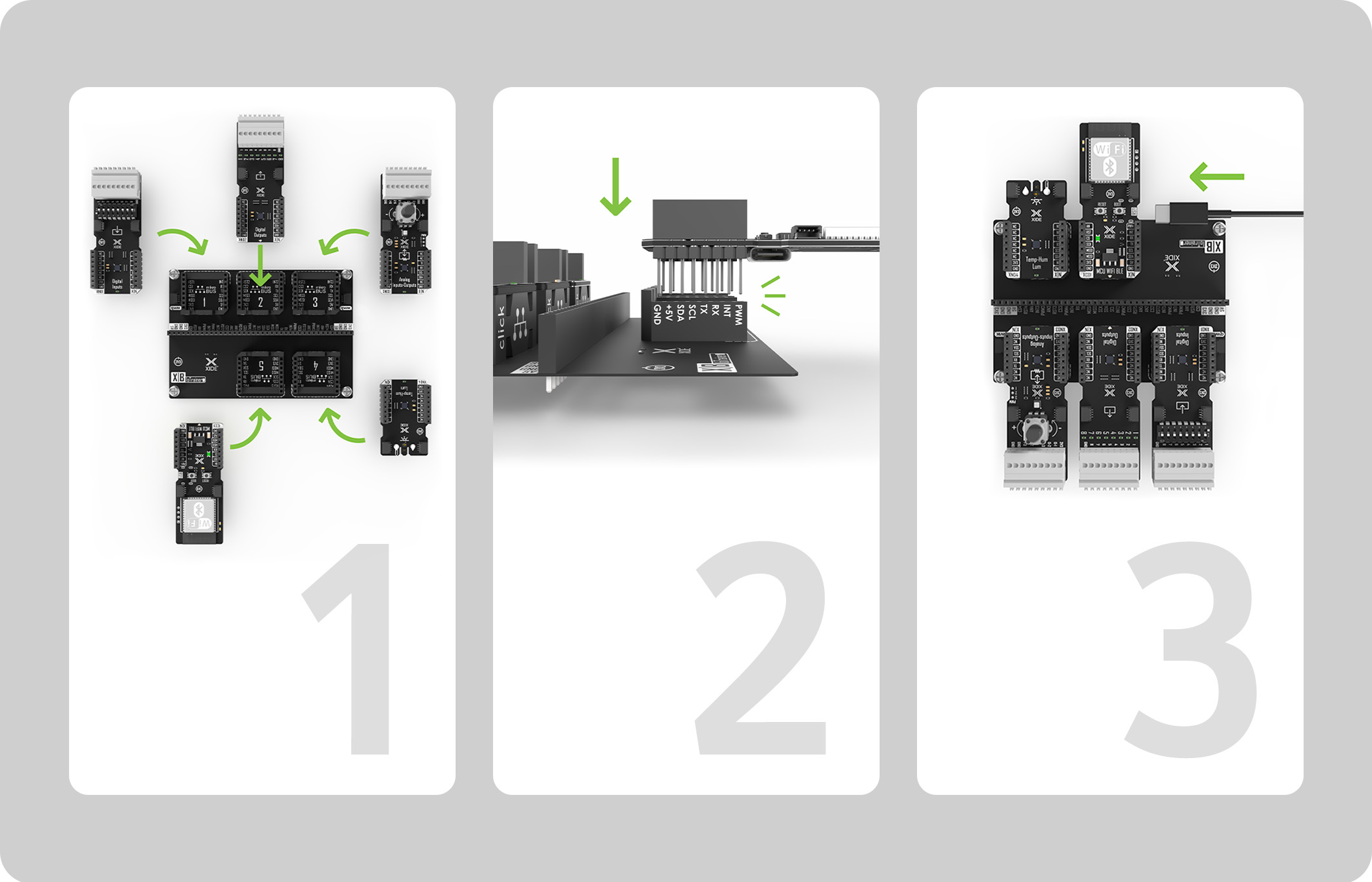
I. Prepare Your Hardware
Assemble the hardware kit, place all the X-NODEs in one of the X-BOARD's mikroBUS™ sockets, placement order is not important, however, make sure the XC01 USB-C connector is not blocked in order to program and power the board. If you don't have an X-BOARD you can stack all the X-NODEs on top of oneanother.
Before powering the board check that all X-NODEs are correctly placed, misaligments could potentially damage the device.
Once the hardware is assembled, connect it to your computer through the USB cable.
II. Prepare Required Software
Install Arduino IDE or PlatformIO If you are using Arduino IDE, follow the next steps (skip for PlatformIO)
Select the board ESP32S3-Dev-Module and configure it according to this image (see in Blynk.Console)
Select the correct port of your device
Note: *On Arduino IDE, make sure to pick version 2.0.17 or lower on the board manager, higher version might not compile at the time of writting this manual, this issue might be fixed in future updates.
III. Prepare the Firmware and Upload It to Your Device
You need to specify the Blynk TemplateID in your firmware. This information will be provided, alongside a sketch to program the device.
Click on the Activate device action in Template Home tab (this tab should open automatically once you've pressed the Use Blueprint button)
Download zip arhive
Flash your device
For Arduino IDE: Go to Sketch > Add File > Select sketch from the zip archive > Press Upload button
For PlatformIO: Open project > Press PlatformIO: Upload
Check the Troubleshooting section at the end of this tutorial if you have issues uploading the firmware
IV. Connect your device to your WiFi network
For this step you need to download Blynk App on your mobile phone
Scan a QR code to start the device activation process in the app
In the app click Start
Connect to "Blynk ... " network
Select network your device will use and click Continue
Your device is connected now! Click Finish to open your device. You also will see your device in the Blynk Console
Explore your device on Blynk Console and Blynk App
V. Set Up Notifications
Let's configure notifications on your phone to keep you informed when the temperature or humidity falls outside the comfortable range. This way, you can take action to restore optimal levels as soon as possible.
Go to the Automations tab
Click +Create automation and choose Device state
Select your device, then the datastream that will trigger the notification, for this example choose Temperature
Select one of the conditions that will trigger the notification and set a value to compare against, for example, is greater than or equal to... 30°C.
Click on + Add Action, then Send an app notfication, set a title and a message for the notification
Choose a name and cover for the automation then click Save
Explore XIDE Documentation and learn how to work with X-NODEs to quickly build IoT projects
Build your own hardware solution with XIDE
Deploy more devices
Troubleshooting
There is multiple compile errors on Arduino IDE
Make sure to pick version 2.0.17 or lower on the board manager, higher version might not compile at the time of writting this manual, this issue might be fixed in future updates.
On the Library Manager pick version 1.3.2 or higher for the Blynk Library
Check if the serial port exist, on the Arduino IDE check the Serial Ports with the XC01 disconnected, then connect it to the computer with the USB cable, check again, if no new Serial Port shows up, on the XC01 press and hold the Boot Button, press and release the Reset Button, if still does not show up try with a different USB cable and port.
If the serial port is available but cannot be open, then using the Arduino IDE's Serial Monitor try opening the serial port, if the port is busy make sure no other app on your computer has it opened, try disconnecting and connecting again the XC01.
How to Reset a Device Configuration
If your mobile device does not detect the Blynk network, then you most likely need to reset the configuration of your ESP32. Follow the steps below.
Open the serial port terminal.
Press and hold the Boot button on your ESP32 for 10 seconds. The serial port monitor terminal should display the following message:
[XXXXX] Hold the button for 10 seconds to reset the configuration…
After 10 seconds, release the Boot button. You should see the following in the terminal:
Search the Blynk network againwith your mobile device using the QR code.
The potentiometer changes the value of ADC1, ADC2 and ADC3 datastreams as well
When there is nothing connected to the analog inputs of the XN03 there will be a ghost reading between the analog inputs and the potentiometer, this is due to the multiplexed nature of the ADC, once a signal is connected to an input it will show the correct value.
Data is updated at very irregular intervals
This blueprint tries to make the most out of free accounts which have a hard cap of device messages, with up to 19 datastreams it would run out relatively fast, to keep a reasonable system responsiveness and data usage, it will only update data once a datastream has changed in a noticeable way. You can upgrade your account and modify the firmware to remove this limit, however, be reasonable with the amount of data sent to the cloud at the same time, as too much data may cause other set of issues, for example the flood error.


.png)


